Appendix F - RTU Control Blocks
The following general-purpose control block algorithms are used in the 25x86 Logic Processor RTU.
· ANNC16 - Annunciator Panel Driver.
· ANDOR - Boolean AND, OR
· AVG - Analog Average/Minimum/Maximum
· BCD 16-Bit - Binary Coded Decimal Inputs to Analog
· CALC - Calculate Point Values
· CALC/TRI-STATE - Tri-State DI Calculation
· CPA - Control Point Adjustment (Closed Loop Control)
· CPY - Copy Point Values
· DLY - Time Delay
· HWOA - Hot Water/Outside Air Reset
· IF - If-Then-Else
· PID - PID Control
· DNS - Day/Night Temperature Setback
· DUTY - Duty Cycling
· ECVR - Economizer/Ventilation/Recirculation
· HDCD - Hot Deck/Cold Deck Reset
· OPSTP - Optimum Stop
· OPSTR - Optimum Start
· SSP - Scheduled Set Point
· SSS - Scheduled Start/Stop (Time Scheduled Control)
Various control blocks allow different sensor types. The following sensor types may be defined:
Control Block Sensor Types
NOCONV |
No conversion (instrument units) |
PERCENT |
0 - 100% of 4 - 20 mA |
T30130 |
30 - 130°F temperature sensor |
T20120 |
20 - 120°F temperature sensor |
T40120 |
40 - 120°F temperature sensor |
T40140 |
40 - 140°F temperature sensor |
T32212 |
32 - 212°F temperature sensor |
T30250 |
30 - 250°F temperature sensor |
TM40120 |
40 - 120°F temperature sensor |
TM30130 |
30 - 130°F temperature sensor |
T30250 |
30 - 250°F temperature sensor |
TM30120 |
-30 - 120°F temperature sensor |
T5090 |
50 - 90°F temperature sensor |
T40240 |
40 -240°F temperature sensor |
T50250 |
50 - 250°F temperature sensor |
T4090 |
40 - 90°F temperature sensor |
Examples:
DW 89 |
Number (specific meaning depends on application). |
PERCENT 50 |
50% of 4-20 mA. |
T30130 70 |
Scaled for a 30 - 130° temperature sensor. |
The following control block algorithms are used extensively in the 25x86 Logic Processor.
ANNC16 Annunciator Driver (16-bit point numbers)
The ANNC16 control algorithm is used to drive an annunciator panel, which will display alarms or status locally for system operators.
The ANNC116 control block uses three modes:
Mode = 0, Normal annunciator panel mode
· When an alarm occurs, the light on the panel flashes and an audible alarm output is turned ON
· When the operator presses the acknowledge button, any flashing alarms go to solid ON.
· When the operator presses the reset button, alarms are reevaluated for alarm condition; those that are no longer in alarm are turned OFF.
· A lamp test button turns on all lamps. Since inrush current for starting all lamps simultaneously is very high, lamps are sequenced ON. A sequence delay (in 10 msec increments) can be programmed into the block. If the sequence number is nonzero, it will delay.
Mode = 1, Pump manual start-stop switch operation
· This mode is used to indicate pressing of a Start or Stop button. When the input changes from Off-to-On, the software flashes the associated output. The output can then be overwritten to indicate the status of the equipment. This is particularly effective when a local control panel is used to control a device in a remote RTU. The flashing provides the operator with an indication that the action has been noted by the RTU.
Mode = 2, Annunciator with second horn and no lamp test
This mode acts like Mode 0 except:
· The lamp test DI point becomes a second horn output.
· Alarms are solid-ON instead of flashing.
DB 00 ;INPUT POINT TYPE
DW 0000 ;INPUT 1
DW 0000 ;INPUT 2
DW 0000 ;INPUT 3
DW 0000 ;ACKNOWLEDGE DI
DW 0000 ;RESET DI
DW 0000 ;LAMP TEST DI (IF MODE=2 SECOND HORN OUTPUT DV)
DB 00 ;LAMP TEST DELAY (1 count = 10 msec))
DB 00 ;TEST HORN WITH LAMPS (1=YES)
DB 00 ;MODE 0 = ANNUNCIATOR DRIVER
1 = MANUAL SWITCH DRIVER
2 = SPECIAL ANNUNC DRIVER
DW 0000 ;DV OUTPUT 1
DW 0000 ;DV OUTPUT 2
DW 0000 ;DV OUTPUT 3
DW 0000 ;HORN OUTPUT DV
DB 00 ;ACKNOWLEDGE BIT MAP (Set to zero)
DB 00 ;ALARM BIT MAP (Set to zero)
;
FILL32 ;DO NOT DELETE
;
NOTE: DB (Define Byte) generates an 8-bit data value. DW (Define Word) generates a 16-bit data value.
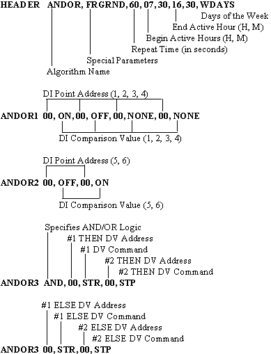
The ANDOR algorithm performs either the logical AND function, or the logical OR function. A maximum of six DI point values are read and tested against six corresponding comparison values. If any two compared values are the same, the result is flagged "true"; otherwise, the result is "false". For the AND function, if all comparisons test "true", the overall result is "true", otherwise the result is "false". For the OR function, if any comparison test is "true", the overall result is "true". If the final overall result is "true", the THEN commands are issued. If the overall result is "false", the ELSE commands are issued.
Analog Average/Minimum/Maximum
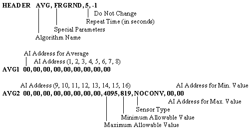
The AVG algorithm calculates the mean (average) of up to 16 AI values and/or determines the minimum and maximum values from a list of AIs. The resultant values are sent to virtual s.
To produce a numerically meaningful average, sensor types must be alike. If a sensor reading goes beyond the set allowable limits, input from the sensor is excluded from the data used. AVG is a non-scheduled algorithm (no time schedule may be defined.)
NOTE: A zero (00) AI address terminates the AI addresses to be read.
Binary Coded Decimal Inputs to Analog
The BCD 16-bit control block enables the reading of BCD digital input points into an analog point. Up to twelve separate 16-bit points can be specified in the control block. If more than twelve are needed, subsequent points must be terminated-in order-from the last point, and the number of points field-changed to the number of input points needed.
The limit of input points is set to 20.
BCD - BINARY CODED DECIMAL INPUTS TO ANALOG
CAN BE USED WITH UP TO 20 INPUT POINTS (PTS 13 etc, MUST FOLLOW IN POINT NUMBER ORDER AFTER POINT 12).
; CB TYPE, STATUS, WINDOW
;HEADER 38H, FRGRND, 5,-1 ;DON'T CHANGE LAST PARAMETER
DB 00 ;NUMBER OF BCD INPUTS (MULTIPLE OF 4)
DW 0000 ;BCD DIGITAL INPUT 1
DW 0000 ;BCD DIGITAL INPUT 2
DW 0000 ;BCD DIGITAL INPUT 3
DW 0000 ;BCD DIGITAL INPUT 4
DW 0000 ;BCD DIGITAL INPUT 5
DW 0000 ;BCD DIGITAL INPUT 6
DW 0000 ;BCD DIGITAL INPUT 7
DW 0000 ;BCD DIGITAL INPUT 8
DW 0000 ;BCD DIGITAL INPUT 9
DW 0000 ;BCD DIGITAL INPUT 10
DW 0000 ;ANALOG OUTPUT PT NUMBER
;
FILL32 ;DO NOT DELETE
;
The CALC algorithm performs signed 16-bit arithmetic on point values and constant values. In addition to the (4) basic math operations (+, -, /, *), CALC does selection, choosing the largest or smallest value from the last operation result or next listed point value. CALC can perform comparisons of values, such as "Greater than" and "Less Than". The algorithm evaluates the block one operation at a time, and no precedence is given to any operator.
The first operator listed must be BEGIN, which means read the value of the following point. Each consecutive operation is performed on result of the previous calculation. The block must end in a SETEQU for it to be meaningful. Between the BEGIN and the final SETEQU there can be a maximum of (5) operations (which could include an intermediate SETEQU).
CALC is a non-scheduled algorithm (no time schedule can be defined).
CALC Control Block Point Operators
BEGIN |
Start: Read the value of the following point. |
PLUS |
Addition: Add the value of following point to the result of previous operation. The result is now used for the next operation. |
MINUS |
Subtraction: Subtract the value of following point from the result of previous operation. |
MULTBY |
Multiplication: Multiply the value of following point to the result of previous operation. |
DIVBY |
Division: Divide the result of the previous operation by the value of the following point. The result is now used for the next operation. |
SELHI |
Select Highest Value: Select the higher of the following items. |
SELLO |
Select Lowest Value: Select the lower of the following items. |
SQRT |
Square Root: Multiply the result of the previous operation by the following value, then take the square root. The following value is usually a numeric constant (NMTYPE). |
SETEQU |
Output: The result of the previous operation is written to the following point. The result remains unchanged. |
CLEAR |
New calculation: Discard the previous result. Read the values of the following point for the next operation. (Use CLEAR after a SETEQU operation to begin a new calculation in the same control block. The limit of 7 operations in a CALC block still applies.) |
CMPGT |
Compare the result of the previous operation to the value of the following point. If the result is greater than the value, the new result is set to 1. Otherwise, the new result is set to 0. |
CMPGE |
Compare the result of the previous operation to the value of the following point. If the result is greater than the value, the new result is set to 1. Otherwise, the new result is set to 0. |
CMPLT |
Compare the result of the previous operation to the value of the following point. If the result is less than the value, the new result is set to 1. Otherwise, the new result is set to 0. |
CMPLE |
Compare the result of the previous operation to the value of the following point. If the result is less than or equal to the value, the new result is set to 1. Otherwise, the new result is set to 0. |
CMPEQ |
Compare the result of the previous operation to the value of the following point. If the result is equal to the value, the new result is set to 1. Otherwise, the new result is set to 0. |
CMPNE |
Compare the result of the previous operation to the value of the following point. If the result is not equal to the value, the new result is set to 1. Otherwise, the new result is set to 0. |
CALC Control Block Point Types
AITYPE |
Analog Input |
AOTYPE |
Analog Output |
CITYPE |
Counter Input |
CZTYPE |
Counter Input (Read/Reset) |
DITYPE |
Digital Input |
DV TYPE |
Device (START/STOP) Output |
FOTYPE |
Flash Output |
NMTYPE |
Numeric Constant |
POTYPE |
Pulse (RAISE/LOWER) Output |
SPTYPE |
Setpoint Output |
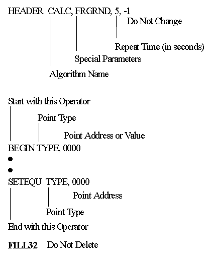
NOTE: To use CALC properly, remember the following items:
1. Writing (SETEQU) to a NMTYPE is not meaningful, and should not be done.
2. CALC deals only in terms of converter counts (NOT engineering units).
The following table lists rules for reading/writing to/from binary points.
Binary Point Operations
|
|
READ OPERATIONS |
WRITE OPERATIONS | ||
Value |
State |
Value |
State | |
DI |
0
|
OFF
|
0
|
OFF
|
DV |
0
|
Last command was STP
|
0
|
Does not change value. (No command)
|
CALC Example 1
DI State Inversion: This example inverts the state of DI#25. The inverted state is written to DI#89. (DI#89 must be a virtual DI.)
CALC - CALCULATE POINT VALUE
HEADER CALC, FRGRND, 1, -1 ;Do not change this last parameter.
BEGIN NMTYPE, 1 ;Start block with this
MINUS DITYPE, 25
SETEQU DITYPE, 89 ;End block with this.
FILL32 ;Do not delete
CALC Example 2a
Conditional Stop: If AI#1 > SP#1, stop DV#1.
CALC - CALCULATE POINT VALUE
IF AI#1 > SP#1
THEN STOP DV#1
ELSE NO COMMAND
HEADER CALC, FRGRND, 5, -1 ;Do not change this last parameter.
BEGIN SPTYPE, 1 ;Start block with this
MINUS AITYPE, 1
SELLO NMTYPE, 0
SETEQU DVTYPE, 1 ;End block with this.
FILL32 ;Do not delete
Conditional Start/Stop: If AI#1 > SP#1, stop DV#1. If this is not the case, start DV#1.
CALC - CALCULATE POINT VALUE
IF AI#1 > SP#1
THEN STOP DV#1
ELSE START DV#1
HEADER CALC, FRGRND, 5, -1 ;Do not change this last parameter.
BEGIN SPTYPE, 1 ;Start block with this
MINUS AITYPE, 1
SETEQU DVTYPE, 1 ;End block with this.
FILL32 ;Do not delete
Device ON Count: DIs numbered 26 - 30 will be used as device status indicators. Adding together the DI states results in the count of devices. AI#49 stores the count. (AI#49 must be a virtual point.)
CALC - CALCULATE POINT VALUE
HEADER CALC, FRGRND, 5, -1 ;Do not change this last parameter.
BEGIN DITYPE, 26 ;Start block with this
PLUS DITYPE, 27
PLUS DITYPE, 28
PLUS DITYPE, 29
PLUS DITYPE, 30
SETEQU AITYPE, 49 ;End block with this
FILL32 ;Do not delete
Conditional Start: If device 1 is ON, start devices 2,3,4,5, and 6.
CALC - CALCULATE POINT VALUE
HEADER CALC, FRGRND, 5, -1 ;Do not change this last parameter.
BEGIN DVTYPE, 1 ;Start block with this
SETEQU DVTYPE, 2
SETEQU DVTYPE, 3
SETEQU DVTYPE, 4
SETEQU DVTYPE, 5
SETEQU DVTYPE, 6
FILL32 ;Do not delete
Copy Point: This block copies SP#1 to AO#1, and DI#25 to DI#49.
CALC - CALCULATE POINT VALUE
HEADER CALC, FRGRND, 5, -1 ;Do not change this last parameter.
BEGIN SPTYPE, 1 ;Start block with this
SETEQU AOTYPE, 1
CLEAR DITYPE, 25
SETEQU DITYPE, 49
FILL32 ;Do not delete
NOTE: This one block performs two completely unrelated operations.
Unilateral Copy: If DI#25 is ON, Start DV#1, Else no command. This type of block is useful when the logic to stop the device is different than that used to start it.
CALC - CALCULATE POINT VALUE
IF DI#25 is ON
THEN START DV#1
ELSE NO COMMAND
HEADER CALC, FRGRND, 1, -1 ;Do not change this last parameter.
BEGIN DITYPE, 25 ;Start block with this
SETEQU DVTYPE, 1
FILL32 ;Do not delete
Comparison: If AI#5 _ 2456, turn on DI#129, otherwise turn off DI#129.
CALC - CALCULATE POINT VALUE
IF AI#5 _ 2456 (50%)
THEN DI#129 = 1
ELSE DI#129 = 0
HEADER CALC, FRGRND, 5, -1 ;Do not change this last parameter.
BEGIN AITYPE, 5
CMPGT NMTYPE, 2456
SETEQU DVTYPE, 129
FILL32 ;Do not delete
The CALC/TRI algorithm indicates the "open", "closed", or "intermediate" states of a discrete input. Typically, this would be used with a slow-acting valve with a limit switch at each end of its range of motion. During the change from fully-open to fully-closed, the valve would be in its intermediate state.
Tri-state values are listed in the following table:
Tri-State Valve Positions
Position |
Meaning |
0 |
Closed |
1 |
Open |
2 |
Intermediate |
-1 |
Both switches active, illegal |
CALC/TRI-STATE is a special use of the CALC algorithm described previously.
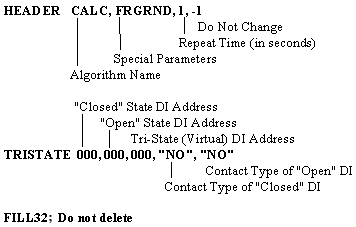
NOTE: "NO" (Normally Open), and "NC" (Normally Closed) must be enclosed in quotation marks.
CPA
Control Point Adjustment (Closed Loop Control)
The CPA algorithm compares the specified SP and AI point values, and uses the result to determine changes in the pulse duration of the output DV. The Gain and Response Time Lag values control the degree to which each effect the output. CPA is a non-scheduled algorithm (no time schedule can be defined.)
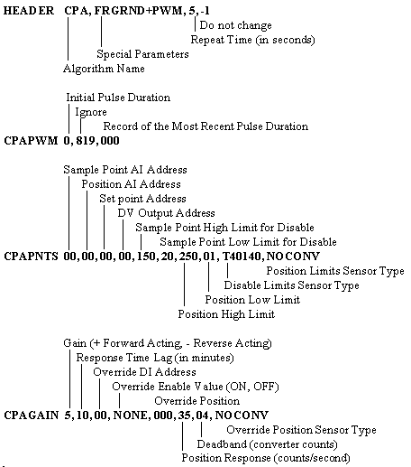
CPA Input/Output Parameters
Set point SP Address: Address (point number) of the SP (set point) that contains the target value for the sample point input.
Sample Point AI Address: Address of the AI (analog input) point controlled by the CPA algorithm. The sample point input is commonly referred to as the "controlled variable" or the "process variable".
Sample Point High and Low Disable Limits: Exist mainly to detect a sensor failure. If the sample point value is outside the limits, the control block interprets this as a sensor malfunction and temporarily disables itself until the value is within limits again. Usually, the sample point high and low limits are set beyond the limits that the sensor can measure. For example, with a 20 - 120° temperature sensor generating a 4 - 20 mA signal, the high and low limits might be set to 10 and 130°. The high limit merely ensures that the control block will not be disabled by a legitimate 120° reading. The low limit disables the control block if the connecting wire to the sensor breaks.
Gain: Represents the percent change of the sample point value (in per cent of full scale 4 - 20 mA) that results from an output pulse of one second. (Allowable values range from -127 to +127.)
Lag: Represents the time duration (in minutes) from the initial occurrence of an output pulse until the sample point finishes responding to that pulse. If the process variable is slow acting, lag is necessary so that the control loop does not try to correct all of the error at one time. (Allowable values range from 0 to 33. If lag is set to zero, the repeat rate is used for lag, giving effectively no lag).
Position Input Address: Address of the AI (analog input) value directly affected by pulses sent to the output point. It represents the position of the actuator, valve, damper, or other physical devices, which in turn affect the sample point input. The position input is commonly referred to as the "manipulated variable".
Position High and Low Limits: Limit travel of the actuator. For example, an outside air damper can be prevented from closing all the way by setting its limits accordingly.
· If the Position Input Address is not specified (i.e., zero), these values represent the limits of the output pulse duration in tenths of a second and the Position Limit Sensor type should be set to NOCONV. This type of limit is associated with the Pulse-Width Modulated output mode.
· If the Position Input Address is specified (non-zero), the values used specify the limits on the actuator indicated by that Input Address and the Position Limit Sensor type should be set to PERCENT. This type of limit is associated with the Raise/Lower output mode. The algorithm modifies the output pulse duration to avoid driving the position input past the limit if the position input is approaching one of its limits.
Deadband: Specifies (in converter counts) how close the sample point must get to the set point before no further control is required.
Output: Address of the DV (device or digital output) point that the CPA algorithm pulses in order to move the actuator.
Position Response: Represents the change of position input value--in converter counts--, which results from an output pulse of one second (associated only with the Raise/Lower output mode, not with the Pulse-width Modulated output mode). This value is needed because various types of CPA hardware move different amounts when pulsed for one second.
Position response is used only if a position input address is specified. It is used to:
· Limit the output pulse duration to prevent the position input value from exceeding the position limits
· Calculate pulse duration when performing position control
· Calculate pulse duration when performing override control.
Override Input Address: Specifies address of the DI (digital input) point which activates override control.
Override Enable Value: activated if the Override Input Address value equals the Override Enable value (ON or OFF).
Override Position: Forces the CPA Pulse Width algorithm to ignore the set point, sample point, and position limits when override control is activated. Also forces the CPA RAISE/LOWER algorithm to drive the actuator to the desired active position when override control is active.
CPA Control Modes
Temperature Control with RAISE/LOWER Output (with Position Input): The most flexible algorithm, allowing the use of all of the available inputs. All input/output parameters must be specified, except those used for override control, which are optional. Position limits still apply in this mode.
The basic calculation performed by the CPA algorithm is:
ERROR = SET POINT - SAMPLE POINT
PULSE DURATION = ERROR * REPEAT TIME * GAIN / LAG
With suitable correction for the fact that PULSE DURATION is in tenths of a second, REPEAT TIME is in seconds, and LAG is in minutes.
Temperature Control with RAISE/LOWER Output (without Position Input): The required parameters are set point input, sample point input, point limits, gain, lag, deadband, and output address. Position input and override input address must be set to zero.
This is the simplest mode of CPA operation in that it requires the fewest inputs. However, it has several drawbacks:
Due to the lack of position information, if for any reason the set point cannot be met, the CPA algorithm will continue to pulse the output even after the actuator has reached its physical limit of travel.
Override control cannot be performed.
Lack of position information also increases the difficulty of trouble shooting control problems during system startup.
Position Control with RAISE/LOWER Output: Used for the case when the Sample Point Address equals the Position Input Address. The Gain and Lag values are ignored and the Position Response is used to calculate the output pulse duration. (Position limits still apply in this mode.)
ERROR = SET POINT - SAMPLE POINT
PULSE DURATION = ERROR / POSITION RESPONSE
Override Control: Provides a means of the CPA algorithm to ignore the set point value and either drive the position input to match the override position value, or perform no control at all.
This control mode is activated whenever the override input value equals the override enable value. If the override position is greater than or equal to -25% (i.e. a positive converter count value), the position input will be driven to match the override position. If the override position is less than -25%, (i.e., a negative converter count value), no commands will be issued to the output point.
The CPA output mode is specified in the control block header.
Pulse-Width Modulated Output: Pulse duration determines the position of the actuator from an initial zero position.
Raise/Lower Output: Pulse duration determines the distance to be traveled by the actuator.
Start/Stop Output: Used in conjunction with the Temperature Control with RAISE/LOWER Output (without Position Input) control mode. A RAISE command is changed into a START command and a LOWER command is changed into a STOP command.
The CPY algorithm copies a value from one point to another point, or the set of values from a block of points to another block of points. A maximum of five points or blocks of points can be copied at a time. CPY is a non-scheduled algorithm (no time schedule can be defined.)
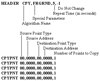
Notes:
1. |
All parameter fields must be filled. |
2. |
A zero (00) point address terminates the addresses to be read. |
3. |
Copies among analog types (AI, AO, SP) work. |
4. |
Copies from analog types to start/stop outputs (DV) work. The sign and value determine the command issued to the DV: |
5. |
Copies from analog types to pulsed outputs (PO) work. The low order byte of the value used is treated as a pulse duration. The sign of the value determines the command: |
6. |
Copies from start/stop outputs (DV) to digital inputs (DI) work. |
7. |
Copies from DI's to DV's work. (If the DV is configured with a pulse duration greater than the repeat time of the control block, the DV will stay on as long as the DI is on.) OFF correlates to STOP and ON correlates to START. |
The DLY algorithm compares two input values to determine if they are equal to each other. Each state ("equal"/"not equal") has a source value, a destination point and a programmable time duration associated with it. This time delay determines the length of time a state must be "true" before further action is taken. In each state, after the time delay expires, the source value is copied to its corresponding destination point.
Table F- 1 Valid Point Types
AITYPE |
Analog Input |
AOTYPE |
Analog Output |
CITYPE |
Counter Input |
CZTYPE |
Counter In (Read/Reset) |
DITYPE |
Digital Input |
DVTYPE |
Device (STR/STP) Output |
FOTYPE |
Flash Output |
NMTYPE |
Numeric Constant Output |
POTYPE |
Pulse (RAI/LO) Output |
SPTYPE |
Setpoint Output |
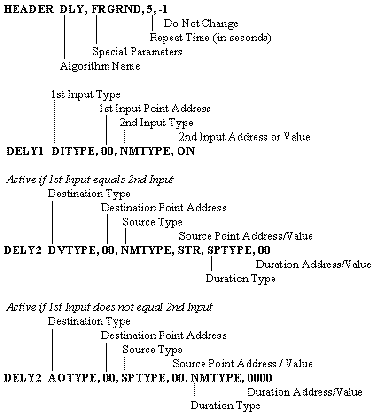
All time duration's are in seconds.
The second input type, the source types, and the duration types, can be omitted and will default to "NMTYPE" with a value specified in the following control block parameter field (rather than the value of a point).
STR and STP can be used as NMTYPE source values for DVs to issue Start and Stop commands. ON and OFF (1 and 0) can be used as values for DIs.
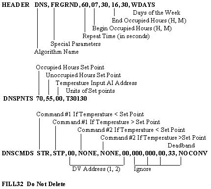
The DNS algorithm reduces the energy required by HVAC systems for heating or cooling by changing the temperature set point values according to the building occupancy schedules. During unoccupied hours, the algorithm lowers the zone heating set point, or raises the zone cooling set point. In this fashion, the zone temperature can be reduced from the normal winter inside temperature to a lower zone temperature, conserving energy. In zones that require air conditioning during unoccupied hours, the normal temperature setting is reset upwards to a temperature that is compatible with the zone requirements.
NOTE: This algorithm would not be applicable to systems where 24-hour settings are mandated.
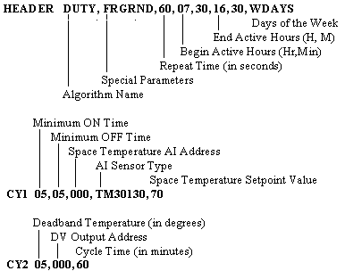
The DUTY algorithm activates and deactivates HVAC equipment for pre-set short periods of time during the normal building operating hours. Systems are periodically cycled off for a short period of time to conserve energy. Typically, this is a few minutes (10-15) out of each hour of operation. The off-time length, and its frequency of occurrence are program adjustable. Nominal off-time is decreased if zone comfort temperature conditions are not satisfied, or increased if zone comfort temperature conditions remain satisfied.
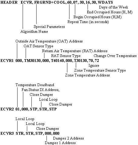
Economizer/Ventilation/Recirculation
In the HVAC Economizer (occupied) mode, the ECVR algorithm utilizes outside air to reduce the building's cooling requirements when the outside air temperature is less than the return air temperature. When the outside air temperature is above the return air temperature or changeover setpoint, the use of outside air in the system is minimized. When the outside air temperature is below the changeover setpoint temperature, outside air is used to maintain the required mixed air temperature.
In the HVAC Ventilation/Recirculation mode, the ECVR algorithm reduces the thermal load during warm-up and cool-down cycles prior to occupancy of the building. During cool-down, when the OAT is cooler than the space temperature, it is used in the cooling cycle. During winter warm-up cycle operation, if the OAT is warmer than the space temperature, it is used in the warming process.
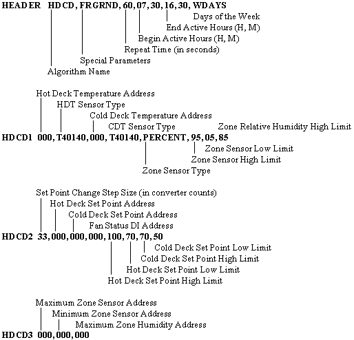
The HDCD algorithm is applied to dual duct systems and multi-zone HVAC systems. Dual duct systems utilize both a heating and a cooling surface (known as Hot and Cold Decks) to provide simultaneous eating and cooling capabilities. Mixing boxes combine hot and cold air streams to satisfy each individual zone temperature requirements. The algorithm evaluates each of the separate temperature zones to determine which two have the greatest heating and cooling demands. Hot deck and cold deck temperature differentials are calculated to meet minimum and maximum zone temperature requirements, thereby maximizing system efficiency. Mixing box positions or space zone temperatures are used to determine the minimum and maximum deck temperatures required to create the desired zone temperature during the "active" hours periods.
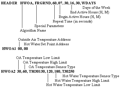
Hot Water/Outside Air Reset (Linear Scaling)
The HWOA algorithm controls the Hot Water Temperature as a function of the Outside Air Temperature (OAT). Between the OAT High and Low Limits, set point values vary in inverse proportion to the Outside Air Temperature. If the OAT is less than the OAT Low Limit value, the set point is clamped to the Hot Water High Limit value. If the OAT is greater than OAT High Limit value, the set point is clamped to the Hot Water Low Limit value. Energy use is minimized as the reduction in the hot water supply temperature results in a reduction of heat loss from equipment and piping.
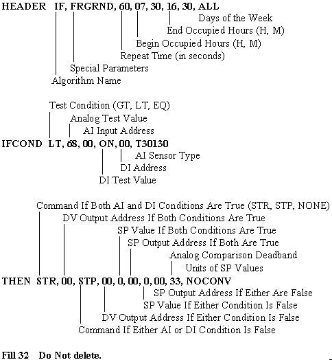
The IF algorithm performs Logical If-Then-Else conditional control. Either an AI (analog) comparison test, or a DI (digital) comparison test, or both may be performed by the control block. For the example below, user-defined information is shown in parentheses.
Example:
IF (Zone Temperature 1) < (68°) AND (Steam Valve 1) is (Open)
THEN (Start)(Unit Heater1)
ELSE (Stop)(Unit Heater 1)
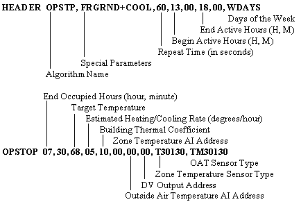
The OPSTP algorithm determines the most advantageous stop time for HVAC equipment. It automatically schedules the optimum (earliest) equipment stop time at the end of the active period, taking into account the Outside Air Temperature (OAT) conditions, current zone temperatures and the thermal inertia of the structure.
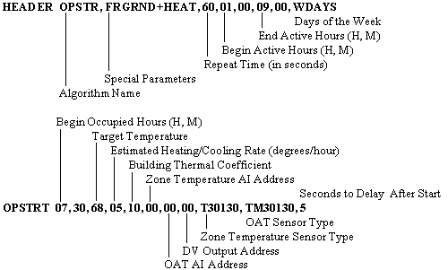
The OPSTR algorithm determines the most advantageous start time for HVAC equipment. It automatically schedules optimum "last moment" start times prior to building occupancy, taking into account the Outside Air Temperature (OAT) conditions, current zone temperatures and the thermal inertia of the structure. The algorithm determines the minimum system time needed to "warm-up" or "cool-down" the building to the target temperature at the start of the occupied cycle.
A programmable time delay can be specified for this control block to reduce power surges at equipment startup.
Proportional/Integral/Derivative (Closed Loop)
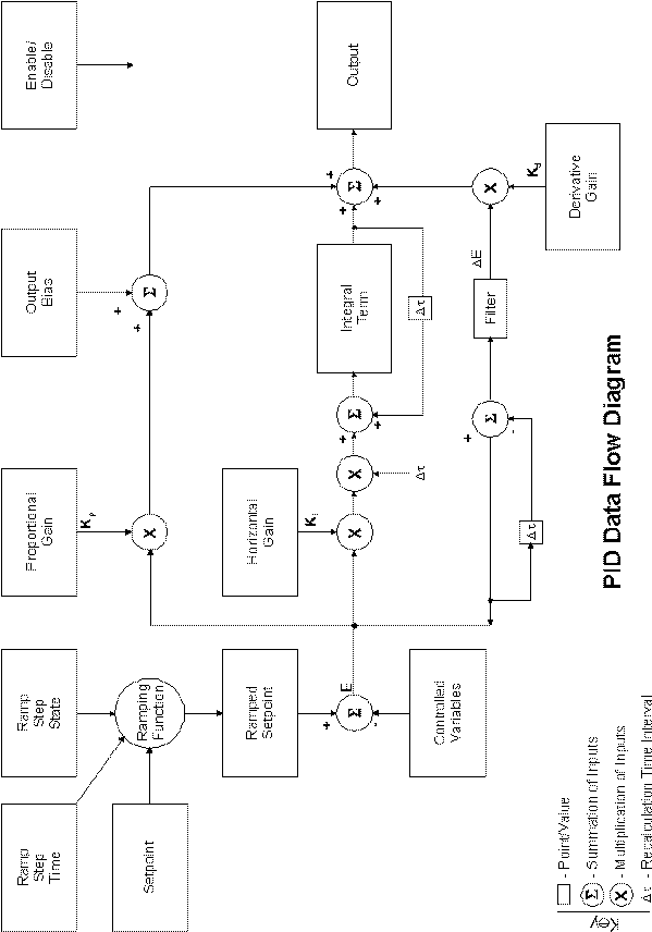
The PID algorithm executes closed loop proportional/integral/derivative control. Each controller mode can be used singly or in combination to effect smooth changes in the output response. A control mode is characterized by its response to the difference (error) between a desired and the measured value, or the rate of change of this error
· Proportional control is a function of the size (magnitude) of the error.
· Integral control is a function of the behavior of the error over time.
· Derivative control is a function of the rate of change of the error.
For the analog type output, the PID algorithm performs the calculation:
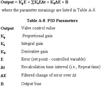
The gain factor for each term controls the degree to which each affects the output. A gain magnitude of zero eliminates that term from the output calculation. Similarly, a gain SP address of 00 also eliminates that particular gain factor from the output calculation.
PID is a non-scheduled algorithm (no time schedule may be defined.)
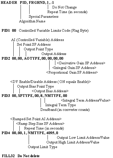
1. Bracketed parameters, < >, are optional given the following conditions.
2. The Integral Gain SP address, or the Proportional Gain SP address must be specified.
3. If the Integral Gain point address is specified (i.e., non-zero), the Integral Term must also be specified. If the Gain point address is not specified, it must be indicated by setting the address to 00.
4. If the Ramped Set Point AI Address is specified, (i.e., non-zero), the Ramp Step Size SP Address and the Repeat Time parameters must also be specified. To indicate that the Ramped Set Point Address is not specified, it is set to 00.
The SSP algorithm controls definition of set point values for a HVAC system which operates on a fixed time of day schedule for each day of the week and during holiday time periods, Three set point values can be defined for each of the occupied and unoccupied time periods. These set point values can be used either as inputs or as comparison values by other control blocks.
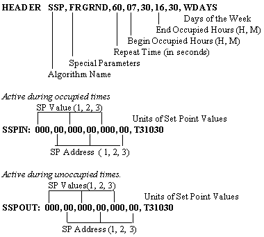
Scheduled Start/Stop (Time Scheduled Control)
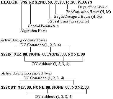
In the SSS algorithm, HVAC systems operate on a fixed time of day schedule for each day of the week and during holiday time periods. Four device commands can be defined (become active) for each of the occupied and unoccupied time periods.
·
SSSD
Scheduled Start/Stop With Delay After Start
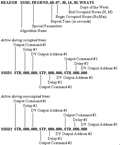
In the SSSD algorithm, HVAC systems operate on a fixed time of day schedule for each day of the week and during the holiday time periods. Three device commands can be defined (become active) for each of the occupied and unoccupied time periods.
A time delay can be specified between consecutive start commands to reduce power requirements at equipment startup.
© 2000 HSQ Technology